logo
  
Band data
 
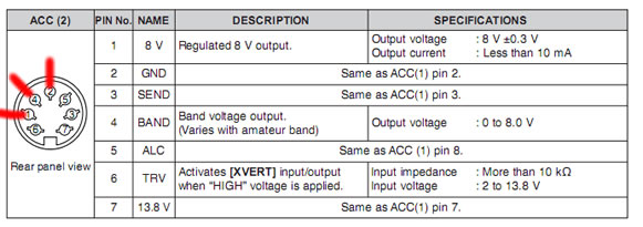
Icom rigs have their own unique way of providing  information to external rigs based on the current band. This information is provided on a single pin on the ACC-2 socket by varying the voltage from 0-8V (see figure below).


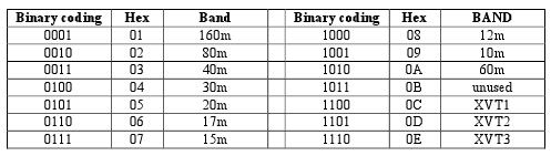
Most peripheral equipment use the ubiquitous YAESU band data method as follows
 
 
This project uses an arduino to read the voltage from the ACC2 pin, determines the band and then converts it to a YAESU band data to use with the many peripherals that support the latter.  As the arduino can sense up to 5V (TTL level) and the icom outputs up to 8V, a voltage divider is required to fool the arduino analog pin that 8V is 5V! Here is the schematic:
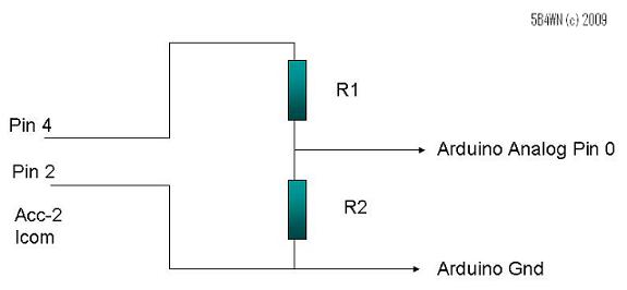


R1=6K
R2=10K
 
Use analog Pin 5 on Arduino
Use Digital Pins 9, 10, 11, 12 for YAESU output DCBA
You can use the Pin 1 for ACC2 to supply the voltage for the arduino
 
 
So this voltage divider converts the Icom voltages as follows:

 Band
 Voltage
 With divider
 160m
 7.0 – 8.0V
 4.3-4.8
 80m
  6.0 – 6.5V
 3.68-4.05
 40m
 5.0 – 5.5V
 3.06-3.43
 30m
 0 – 1.2V
 0
 20m
  4.0 – 4.5V
 2.43-2.81
 17m
 3.0 – 3.5V
 1.81-2.18
 15m
 3.0 – 3.5V
 1.81-2.18
 12m
 2.0 – 2.5V
 1.19-1.56
 10m
 2.0 – 2.5V
 1.19-1.56
 6m
 1.2-2V??
 0.75-1.19
 
So once the circuit is complete, you need to program this using the arduino development environment. Find more about this here
 
Copy and paste the following code:


Arduino Code:
 
//icom band decoder
//Marios Nicolaou 5B4WN (c) 2009 7 24
//Use the code at your OWN risk
//GPL licence
//               .  = gnd
//pins   +    o  =+
//         o       o
//        o         o
int icomBandPin = 5;    // select the input pin for the potentiometer
int realVoltage = 8;  // variable to store the value coming from the sensor Volts
int sensedVoltage=0;
int D=9;
int C=10;
int B=11;
int A=12;
float calculatedVoltage=0;
int band=0;
int counter =0;
int previousValue=0;
 void setup() {
   Serial.begin(9600);
   pinMode(A, OUTPUT);
   pinMode(B, OUTPUT);
   pinMode(C, OUTPUT);
   pinMode(D, OUTPUT);
 }
 void loop() {
   // read the value from the sensor:
   sensedVoltage = analogRead(icomBandPin);    
   
   
   //get 5 consecutive values
//  counter++;
   
   if (counter==5) {
   
   calculatedVoltage = float(sensedVoltage)*5/1024;
   
   Serial.print (sensedVoltage);
   Serial.print (" - ");
   Serial.print (calculatedVoltage);
   Serial.print (" - ");
   band=getBand(calculatedVoltage);
   
   Serial.println(band, DEC);
   delay (20);
                  
 } else {
   if (abs(previousValue-sensedVoltage)>10) {
    //means change or spurious number
     previousValue=sensedVoltage;
   } else {
     counter++;
     previousValue=sensedVoltage;
   }
   
   
 }
 
}
 
int  getBand(float voltage) {
   int band=0;
 
 /*      A   B  C   D
 160     0   0  0   1
80       0   0  1   0
40       0   0  1   1
20       0   1  0   1
15       0   1  1   1
10       1   0  0   1

 */


if (voltage>4.20 && voltage<4.68) {
 band=160;
 digitalWrite(A, LOW);
 digitalWrite(B, LOW);
 digitalWrite(C, LOW);
 digitalWrite(D, HIGH);
 
} else if (voltage>3.50 && voltage<4.20) {
 band=80;
 digitalWrite(A, LOW);
 digitalWrite(B, LOW);
 digitalWrite(C, HIGH);
 digitalWrite(D, LOW);
} else if (voltage>=2.95 && voltage<3.50) {
  band=40;
 digitalWrite(A, LOW);
 digitalWrite(B, LOW);
 digitalWrite(C, HIGH);
 digitalWrite(D, HIGH);
} else if(voltage>=2.30 && voltage<2.95) {
  band=20;
 digitalWrite(A, LOW);
 digitalWrite(B, HIGH);
 digitalWrite(C, LOW);
 digitalWrite(D, HIGH);
 
} else if (voltage>=1.70 && voltage<2.30) {
  band=15;
 digitalWrite(A, LOW);
 digitalWrite(B, HIGH);
 digitalWrite(C, HIGH);
 digitalWrite(D, HIGH);
 
} else if (voltage>=1.2 && voltage<1.7) {
  band=10;
 digitalWrite(A, HIGH);
 digitalWrite(B, LOW);
 digitalWrite(C, LOW);
 digitalWrite(D, HIGH);
 
} else if (voltage>=0.75 && voltage<1.2) {
  band=6;
   digitalWrite(A, LOW);
 digitalWrite(B, HIGH);
 digitalWrite(C, LOW);
 digitalWrite(D, HIGH);
} else if (voltage  <0.75) {
  band=30;
   digitalWrite(A, LOW);
 digitalWrite(B, HIGH);
 digitalWrite(C, LOW);
 digitalWrite(D, LOW);
}
 return band;
 
}
 
 
You can use the inbuilt serial port terminal application within the arduino IDE to debug your board. Use 9600 baud for this and check that the voltages for each band are correct an if necessary adjust the values in the code above.
 
I have built this using an arduino RBBB and a FTDI programming cable. I have tested it in 3 contests now and it has worked without fail.
 
Disclaimer:
Use the information on this page at your OWN RISK. 5B4WN will not be liable to any damage to your equipment that may have resulted from information obtained from this page/website!

WA4SIX has modified the above code for BCD  see here